By analyzing the needs of applications and operating systems, considering
typical instruction mixes, and inspecting application and operating system
traces, the architecture group reached a consensus on the definition of the
PowerPC Architecture. This architecture achieves the goals previously listed,
yet permits POWER customers to run their existing applications on new systems
and to run new applications on their existing systems.
The PowerPC Architecture includes most of the POWER instructions.
Nearly all the excluded POWER instructions are instructions that execute
infrequently and the compiler can replace each excluded instruction by
several other instructions that are in both architectures. The excluded
instructions will cause an Illegal Instruction type Program Interrupt on
PowerPC processors and will be emulated by the AIX operating system. Most
POWER applications will benefit from the improved performance of new PowerPC
processors. Other applications that frequently perform the operations in the
following list, which use the excluded instructions, will produce correct
results on PowerPC systems but may run slowly unless they are recompiled:
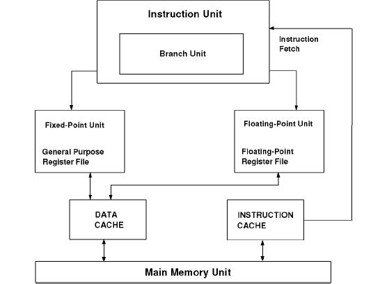
The 620 can fetch issue and complete upto four instructions per clock.There are
six seperate execution units, each of which can initiate execution independently
from its own reservation stations. The six units are as follows:
Integer Units
Complex integer function units
Load Store Unit
Floating Point Unit
Branch Processor Unit
PowerPC: Introduction
Early in 1991, processor architects, compiler experts, operating system
developers, processor designers, system architects, and system designers
from the three companies worked together to develop an architecture that
would meet the needs of the alliance. Because it would have been impossible
to develop a completely new architecture in time to satisfy the needs of
their customers, the companies decided to use the POWER Architecture as the
starting point. They made changes to achieve a number of specific goals.
The architecture had to:
Permit a broad range of implementations, from low-cost controllers to
high-performance processors
Be sufficiently simple so as to permit the design of processors that have
a very short cycle time
Minimize effects that hinder the design of aggressive superscalar
implementations
Include multiprocessor features
Define a 64-bit architecture that is a superset of the 32-bit architecture,
providing application binary compatibility for 32-bit applications
Extended- precision bit string computation
Extended- precision multiplication
Integer division
Generation or modification of instructions about to be executed
The first PowerPC processor, the 601, implements all but two of the nonprivileged POWER instructions. One goal for this bridge processor was to allow application vendors additional time to recompile their products for PowerPC systems. Most existing POWER applications will run well on 601-based systems. Applications that generate or modify code might use the POWER cache flush instruction, which 601 does not implement. Such programs will produce correct results (the operation is emulated by AIX), but they may run slowly without recompilation. As noted previously, the 601 implements nearly all the excluded nonprivileged POWER instructions. However, new applications should not use these excluded instructions as other PowerPC processors will not implement them.
PowerPC Architecture is a 64-bit architecture. This architecture extends addressing and fixed-point computation to 64 bits, and supports dynamic switching between the 64-bit mode and the 32-bit mode. In 32-bit mode, a 64-bit PowerPC processor will execute application binaries compiled for the 32-bit subset architecture. Because a description of the entire architecture is too large to be addressed here, this paper concentrates on the descriptions of the changes that affect the user-mode 32-bit subset architecture.
The PowerPC 620 processor implements the
full 64-bit PowerPC architecture and has a L2 cache controller
embedded in the microprocessor that interfaces with the standard SRAM
chips. It achieves its performance through concurrent execution of up
to four instructions per clock cycle in the following six execution
units: · Three integer units - Two single cycle integer units - One
multiple cycle integer unit · Branch processing unit · Load/store
processing unit · Floating-point processing unit The PowerPC 620 is
targeted at the high-end desktop systems, servers and transaction
processing-based machines. The PowerPC 620 processor will be available
in one model that runs at a clock speed of 133 MHz.
PowerPC620 Architecture
Two integer units XSU0 and XSU1 handle add, subtract, and simple logical operations,
and these operations take 1 cycle
MCFXU handles integer multiplication and division, having a latency of 3 to 20
The LSU handles loads and stores, it is fully pipelined and has its own address
adder. It contains both load and store buffers.
FPU is fully pipelined except for the divide unit.The latencies for multiply and
add are 2 and 31 for the divide.
It completes branches and informs the fetch unit of mis-preditions. It includes the
condition register, used for conditional branches.When condition registers are set
early enough, conditional branches can be executed in parallel with no additional
delay
The 620 operates like the speculative processor with one extension: The register
set is extended with a set of renaming registers.These are used to hold speculative
results untill the instruction commits, at which time the result is written from the
renaming registers to the standard integer or floating point registers. Overall, the
operands are available from a single location: the extended register file, consisting
of the architectural plus renaming registers.The scheme used is: when an instruction
issues,it is allocated a rename register, when execution completes, the result is written
into the rename register, and when it commits it is written to the architectural registers.