In this project you are required to implement an
Asynchronous Transfer Mode (ATM) network layer and a connection-oriented,
reliable ATM adaptation layer (AAL7). The lowest levels of your
code will simulate an ATM switch communicating over physical links
with other ATM switches. You will be provided with a simple file
transfer application (like FTP) that you will link with your code
to support reliable file transfers between nodes across an unreliable
network. This handout provides a detailed specification of the
project, including the definition of the AAL7 service interface
that you must implement, and a list of requirements and checkpoints
you should meet.
The project has two main components. Both components require a significant amount of design work by you, as well as implementation effort. The first part of the project is the implementation of an ATM Network Layer over the UDP connectionless service. The ATM portion of your project will include an implementation of a software switch that supports the sending, receiving, and forwarding of ATM cells, the establishment and teardown of virtual circuits (VC's) through a signalling protocol, and the detection of dead links and adaptive rerouting of virtual circuits through a routing protocol. Links themselves are to be simulated by the exchanging of UDP datagrams between switches.
The second part of the project is the design and implementation of a reliable, connection-oriented ATM Adaptation Layer (AAL7). This layer extends the ATM network layer to support the reliable exchange of messages across the network. Large messages must be segmented into a series of AAL7 packets (shown in Figure 5), sent through the ATM network layer, and reassembled by the receiver, thus requiring you to implement a Segmentation and Reassembly (SAR) protocol.
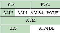
Figure 1: ATM Protocol Layering the big picture.
You will have considerable freedom in designing the interface between AAL7 and your ATM network layer and in designing your signalling, routing, and SAR protocols. However, since you will be linking with code provided to you to implement file transfer, you must adhere rigidly to the AAL7 service interface defined in Section 5 of this document and more formally specified in the form of header files to be made available soon.
All projects must be implemented as a single multi-threaded
process that performs all switch, network layer, adaptation layer,
FTP client, and FTP server (FTPd) functions. Figure 1 gives
an overview of the software components and protocol layers in
a typical implementation. Unshaded portions of Figure 1 are not
part of this project, but represent protocols that could conceptually
be added or substituted at the layer where they are shown.
For this project, each "node" of the ATM network is simulated by a separate execution of your program. Nodes will run on a subset of the AITS Alpha cluster with each node corresponding to a (machine address, UDP port number) pair. Therefore, each executing copy of your program represents a "virtual node" communicating with other virtual nodes through a single UDP port. There may be many such virtual nodes running on a single workstation or running on several workstations.
A configuration file (defined in Section 2.4) specifies the virtual nodes in the ATM network and the links between them. Your program will take as command line arguments the name of the configuration file and the machine name and UDP port number of a virtual node. You will be provided with a script that parses the configuration file and executes (locally or remotely) a copy of your program for each virtual node.
- The ATM Layer
In an ATM network, data is transmitted in small, fixed-size units called cells. Each ATM cell has 5 bytes of header information and 48 bytes of payload (data). The 5 bytes of header are used to route each cell from its source to its destination. The ATM cell header format is shown in Figure .
ATM provides a connection-oriented, but unreliable service for sending and receiving ATM cells. Any mechanisms that you use to provide reliable data transfer will be implemented within the AAL7 layer. It may help to conceptualize the ATM layer as the network layer and AAL7 as a pseudo-transport layer.
Within the network of virtual nodes, ATM maintains a virtual circuit (VC) for each connection. A signalling protocol is used to establish such VC's. Once a VC is established, ATM cells can flow through it from switch to switch, being forwarded across each hop according to their Virtual Channel Identifier (VCI).
You will treat UDP as a link layer, encapsulating ATM cells in UDP datagrams. You can assume that UDP will provide in-order delivery with no duplication. However, since UDP very rarely fails across a LAN, you will not be sending datagrams across raw UDP sockets, but rather through a garbler that randomly introduces errors or cell losses. This will stress-test the reliability mechanisms in your implementation of AAL7.
The ATM Layer is also responsible for making routing decisions based on the connectivity of the network. If a node crashes, virtual circuits that passed through it must be rerouted (if possible) to keep them alive. The choice of a routing protocol and a mechanism for the propagation of routing information is an open design parameter of your project. You may choose to implement a link-state or distance-vector algorithm, or come up with your own design. Whatever routing protocol you choose will require an underlying protocol to detect the failure of links.
- Signalling
Before data can be sent or received through the endpoints of a virtual circuit, an ATM VC must be established. When an application calls atm_connect() or atm_listen() / atm_accept() (see Section 5), a VC must be established. Your job is to implement the signalling protocol that performs such establishment. Every switch along the path from the source node to the destination node must participate in the VC establishment. At each switch along the path, a mapping must be created (and maintained for the lifetime of the VC) from incoming VCI to outgoing VCI. Each cell that flows through a switch first has its cell header modified to contain the new VCI, and is then sent on to the next switch. Each switch must maintain a table with entries similar to that shown in Figure 2. At VC establishment time, an entry must be added to the table. The table is then accessed each time a cell flows through a switch along the VC's path to determine on which link it should be sent out. At VC teardown, the appropriate entry must be removed from each switch's table.

Figure 2: VC Translation Table Entry Example.The signalling protocol used to set up a VC is to be designed by you. You must define the messages that are exchanged (i.e.,. the number of different types of messages, and the formats of the messages), as well as the protocol state machine. Issues you must consider include: the reliable transmission of signalling messages (what happens if a signalling message gets lost), and the allocation of the VCI space (how does a node decide which VCI to use when setting up a VC). You can use a special value of the Payload Type field to indicate that an ATM cell is a signalling protocol message. You can also assume that all signalling messages arrive in order, or do not arrive at all. Thus, you do not need to worry that the network will cause duplication or out-of-order arrival of signalling cells. More information on signalling protocols (and state machines) will be provided in class.
- Routing
In order to fill in the NextHop field of a VC translation table entry (see Figure 2), your VC establishment code will need to access an internal routing table that maps each destination in the network to the virtual node that should be next on the path to it. Your routing protocol needs to build and maintain this table.
When there is a change in network connectivity, your ATM layer must not only construct efficiently-routed virtual circuits whose construction is initiated after the change, but must also attempt to reroute existing virtual circuits. This rerouting must occur before AAL7 times out on the connection and closes it. Therefore, you must think carefully about how to set the timers that initiate your routing protocol. Furthermore, since switches in the middle of a virtual circuit may need to repair a damaged VC, your VC translation table entries may need to be extended to hold information about the end-points of a connection.
- Network Configuration
File
While the connectivity of the network may change over time due to node failures, the topology of the underlying "physical network" as specified by the set of links joining the virtual nodes remains constant. This topology is specified in a network configuration file given to your program on the command line. This file specifies the virtual nodes in the ATM network (i.e., the machine / UDP port pairs that run your program) and the links between them. The format of the network configuration file is shown in Figure 3, while the topology of the network implied by that file is shown in Figure 4. You should use ports from your (or your partner's) assigned ports for each node.
Node 1 (tracy, 5000) links 2
Node 2 (tracy, 5001) links 3 4
Node 3 (tracy, 5002) links 2 4
Node 4 (tracy, 5003) links 2 3
Figure 3: Example Network Configuration File
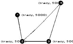
Figure 4: Network Topology.
In order to test that your ATM layer transfers data
reliably, your program will interact with the garbler. The garbler
is a set of routines that intercepts an ATM cell just before it
is sent over a UDP port. The garbler potentially corrupts the
cell or drops it, prior to forwarding it to its destination. To
make life a little easier, the garbler will never corrupt the
ATM cell header. Your signalling protocol and AAL7 need only recover
from lost or corrupted cells, since you are guaranteed no duplicate
or out of order cells. To obtain more information on how your
program should interface with the garbler, see the document available
in the course WWW page.
The AAL7 layer provides a connection-oriented, reliable message transport service that applications like FTP can leverage to communicate over an ATM network. AAL7 does not preserve packet boundaries, which is to say that its interface has byte-stream semantics like TCP.
The endpoint of an AAL7 connection is called a Service
Access Point (SAP). A SAP is simply a combination of a host identifier
and a service identifier. The host identifier specifies a virtual
node on the ATM network, while the service identifier specifies
a particular service on the host system.
You must implement the calls listed below as the
service interface for applications wishing to use your ATM service.
Some of these calls are analogous to BSD UNIX system calls. Looking
at the UNIX man pages for connect() , listen() , and accept()
may help you to understand the ATM service interface calls better.
int aal7_connect(struct aal7_sap *remote_sap)
int aal7_listen(struct aal7_sap *local_sap, int limit)
int aal7_accept(int aal7_sap_desc)
int aal7_send(int aal7_conn_desc, char *packet, int pkt_len)
int aal7_recv(int aal7_conn_desc, char *packet_buf, int max_pkt_len)
int aal7_disconnect(int aal7_conn_desc)
int aal7_setMaxRecvWinSize(int windowsize)
int dump_vc_table()
The aal7_connect() , aal7_listen() , and aal7_accept() calls are used by applications to establish full-duplex, reliable connections between two SAP's. The aal7_send() and aal7_recv() calls are used to exchange data across the connection.
The aal7_connect() call is an active request to establish a connection to a remote SAP; it returns a descriptor (similar to the socket() call), or an error if the connection could not be established. The descriptor can be used in future calls to represent an endpoint of communication. aal7_connect() should block the the caller until it returns.
The aal7_listen() call is used by servers to register a service with the AAL7 layer service by specifying a SAP and the maximum number of outstanding connection requests that are allowed to it. A descriptor is returned by aal7_listen() and is used as the argument to the aal7_accept() call. Note: this descriptor is different than the one returned by aal7_connect() and aal7_accept().
The aal7_accept() call indicates that a server is willing to accept a connection from a client. This call blocks until a connection has been established and returns a descriptor that can be used to communicate with the client that requested the connection.
The aal7_send() and aal7_recv() calls each require a valid connection descriptor (returned by either aal7_connect() or aal7_accept() ) and a pointer into a buffer that either contains an AAL7 packet or is ready to receive one. Since all communication is connection-oriented, a connection descriptor determines the other endpoint involved in the data exchange.
Finally, there are two final calls that are used for diagnostic purposes. The aal7_setMaxRecvWinSize() call is used to adjust AAL7's maximum receive-window size. Your AAL7 layer may assume a default window size, but must provide the application with the ability to change the maximum window size so that your flow-control mechanism can be tested. The last call, dump_vc_table() , causes the underlying ATM switch on a node to display a formatted dump of the current contents of the VC table. You should also print statistics about VC table usage (e.g. the number of active connections, the total number of connections made since initialization, per-VC traffic volume, etc).
All of the calls in the AAL7 service interface may
return error codes to indicate various types of failure (e.g.
a connection establishment timed out, a SAP was already in use,
etc.) The error codes that you must support, as well as the exact
prototypes of the above functions, will be specified in a set
of header files to be made available shortly. The reason for the
rigidity, of course, is that your code must interoperate seamlessly
with the FTP and FTP-daemon application code that will be linked
into your project.
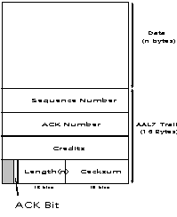
Figure 5: AAL7 Packet Structure.
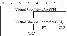
Figure 6: ATM Cell Header.
- Segmentation, Reassembly and Reliability
Your AAL7 layer must perform the segmentation and reassembly of application data messages as well as provide reliable delivery of those messages. An AAL7 packet is created by appending a special trailer to each data message (see Figure 5). The main contributions of AAL7 are the 16-bit checksum it uses to detect data corruption and fields that you will use for flow control. For the data integrity, you may use the checksum used by TCP or you can design your own. After appending a message with the AAL7 trailer, the resulting AAL7 packet must be segmented into ATM cells. The ATM cell header you will use is shown in Figure 6. You will only be concerned with the VCI (virtual channel identifier) and PT (payload type) fields (i.e., all other fields can be set to 0).
While using AAL7, the last 16 bytes of the final cell of a packet must contain the trailer (preceded by padding, if necessary). In addition, the PT field of the last cell must be set to indicate that it is the final cell of the packet. The PT value for end of packet must be 001. On receipt of an AAL7 packet, your AAL7 layer must strip all cell headers, verify the checksum, and, if correct, make the data ready for the appropriate application (with the AAL7 trailer stripped off). If the checksum is incorrect, the packet should be dropped. Note that since you are providing a reliable service to the applications that use your ATM layer, you must also devise some kind of buffering strategy so that you can provide in-order data even when the packets arrive out of order. Note: don't confuse AAL7 packets with ATM cells.
There are many issues that must be addressed in your design of AAL7. In order to provide reliability, you must be able to handle lost or damaged packets. Thus you will need to think about how you want to handle timers, retransmissions, acknowledgments, and flow-control. There are several fields in the AAL7 trailer that can be used for this purpose. Your design document should specify the state machines for your AAL7 implementation. We recommend that you get simple flow-control AAL7 working (i.e., one-packet window) first.
- System Structure
Figure 7 shows an overview of the various components of this project and how they relate to each other. Note that this figure does not dictate the exact system structure that your project should have. The manner in which you structure your program is extremely important. While we are requiring that that you implement all functionality in a single multi-threaded process, you still have considerable design leeway in many areas. Some of the issues that you must decide are: how to assign threads to tasks, how data is going to flow through the various layers of your system, how mutual exclusion will be provided on key data structures, how threads will synchronize with each other.
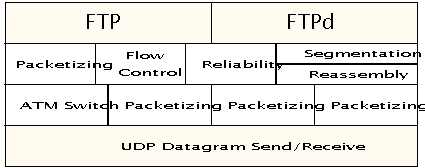
Figure 7: System Components. - Requirements and Checkpoints
You should submit a design proposal that gives a description of how you plan to address the issues raised in the previous sections. We will comment on your design proposal and return it to you for revision. A final version must be submitted soon after. Your design proposal should be as detailed as possible. The better and more detailed the design, the easier it will be to do the implementation. At a minimum, your design proposal should describe the following:
ATM Layer Issues AAL7 Layer Issues
General Issues - Deadlines
The following is a list of required deadlines.
Oct 22 (Wed) Submit draft of design proposal
Nov 7 (Fri) Submit final version of design document
Nov 10 (Mon) Demonstration of status of implementation (show all features for Nov 7)
Dec 11-12 (Th-Fri) Final project demonstration, short final writeup and hand-in of well-documented source code
- Milestones
You should try to follow the checkpoint schedule given below. This will help you avoid falling behind. The checkpoints are for your guidance only.
Nov 7 (Friday)
Timer management
Simple ATM signalling protocol (ignore lost cells)
Simple AAL7 Segmentation/Reassembly with simple flow control (i.e., send/receive windows of size of one)
Nov22 (Tuesday)
Full-fledged AAL7 Segmentation/Reassembly (including full reliability)
Full-fledged ATM signalling protocol (including full reliability, handling broken links)
Dec 2 (Fri)
Adaptive routing, rerouting when a link is broken in the middle of a connection
Garbler incorporated with your code
At the time of the final demonstration, you should hand in a 2-3 page writeup. This should include a working status of your project (what works and what, if anything, doesn't). This report should describe the features of your implementation that you feel are most important (and distinguish your implementation from others). It should also describe any significant changes in the design from the final design document.
The final design document, final demonstration and writeup will contribute to the project grade. For the final demo you will demonstrate the FTP application (with your ATM Network Layer) using a network configuration file supplied by us. So, be sure you obey the format specified earlier in this document.