|
|
|
|
|
|
|
|
|
|
|
|
|
|
|
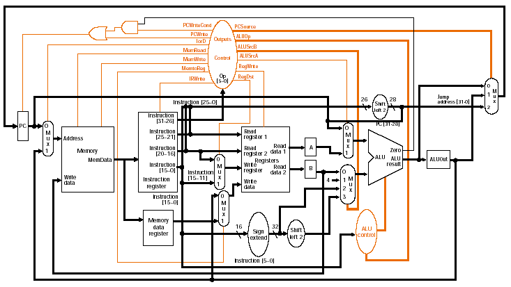
Multi-cycle datapath:
ALU, memory address, or branch |
|
|
|
|
|
|
|
|
|
|
|
|
|
|
|
|
|
|
|
|
|
|
|
|
|
|
|
|
|
|
|
|
|
|
|
|
|
|
|
3. R-type execution,
memory address computation, or branch |
|
Fig. 5.33 |
|
|
ALU operates on the
operands, depending on class of instruction |
|
|
|
Memory reference: |
|
|
|
|
ALUOut = A + sign_extend
(IR[15-0]); |
|
|
|
|
Operation: ALU creates
memory address by adding operands |
|
|
|
|
Control signals |
|
|
|
|
|
|
|
ALUSrcA = 1: register A |
|
|
|
|
|
ALUSrcB = 10:
sign-extension unit output |
|
|
|
ALUOp = 00: add |
|
|
|
|
|
|
Arithmetic-logical
operation (R-type): |
|
|
|
|
|
ALUOut = A op B; |
|
|
|
Operation: |
|
|
|
ALU performs operation
specified by function code on values in registers A, B |
|
|
(Where did these operands
come from? |
|
|
|
They were read from the register file on
the previous cycle.) |
|
|
|
Control signals |
|
|
|
ALUSrcA = 1: register A |
|
|
|
ALUSrcB = 00: register B |
|
|
|
|
ALUOp = 10: use function
code bits to determine ALU control |
|
|
|
Branch: |
|
|
|
If (A == B) PC = ALUOut; |
|
|
|
Operation: |
|
|
|
ALU compares A and
B. If equal, Zero output signal is
set to cause branch, |
|
|
|
and PC is updated with
branch address |
|
|
|
Control signals |
|
|
|
ALUSrcA = 1: register A |
|
|
|
ALUSrcB = 00: register B |
|
|
|
ALUOp = 01: subtract |
|
|
|
PCWriteCond = 1: update
PC if Zero signal is 1 |
|
|
|
PCSource = 01: ALUOut |
|
|
|
(What is in ALUOut, and
how did it get there? |
|
|
|
It's the branch address calculated from the
previous cycle, NOT the result of A - B. |
|
Why not?
Because ALUOut is updated at the END of each cycle.) |
|
|
|
Note that PC is actually
updated twice if the branch is taken: |
|
|
|
Output
of the ALU in the previous cycle (instruction decode/register fetch), |
|
From ALUOut if A and B
are equal |
|
|
|
Could
this cause any problems? No, because
only the last value of PC |
|
|
|
is used for the next
instruction execution. |
|
|
|
Jump: |
|
|
|
|
PC = PC[31-28] ||
(IR[25-0] << 2); |
|
|
|
Operation: |
|
|
|
PC is replaced by jump
address. |
|
|
|
(Upper
4 bits of PC are concatenated with 26-bit address field of instruction |
|
|
|
shifted left by 2 bits) |
|
|
|
Control signals |
|
|
|
PCSource = 10: jump
address |
|
|
|
PCWrite = 1: update PC |
|
|
|
(Where did the jump
address come from? |
|
|
|
Output of shifter
concatenated with upper 4 bits of PC.) |
|
|
|
|
|
|
|
|
|
|
|
|
|
|
|
|
|
|
|
|