|
|
|
|
|
|
|
|
|
|
|
|
|
|
|
|
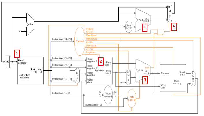
Datapath: branch |
|
|
|
|
|
|
|
|
|
|
|
|
|
|
|
|
|
|
|
|
|
|
|
|
|
|
|
|
|
|
|
|
|
|
|
|
|
|
|
|
|
|
|
|
|
|
|
|
|
|
|
|
|
|
|
|
|
|
|
|
|
|
|
|
|
|
|
|
|
|
|
|
|
|
|
|
|
|
|
|
|
|
|
|
|
|
|
|
|
|
|
|
|
|
|
|
|
|
|
|
|
|
|
|
|
|
|
|
|
|
|
|
|
|
|
|
1. Fetch instruction and
increment PC |
|
|
Fig. 5.21 |
|
|
|
2. Read 2 registers from
register file for comparison |
|
|
|
|
3. ALU subtracts data
values, using ALU control to select operation and ALUSrc = 0 |
|
|
|
4.
Generate branch address: add (PC + 4) to sign-extended offset, shifted left
by 2 |
|
|
|
why shifted by 2? what control signal values? |
|
|
|
|
|
5. Use Zero output from
ALU (and Branch control) to determine which result to use to update PC |
|
If equal, use branch
address |
|
|
|
|
|
else use incremented PC |
|
|
|
|
Note that this is all
happening simultaneously in 1 clock cycle (adder separate from ALU) |
|
|
|
|
|
|
|
|
|
|
|
|
|
|
|
|
|
|
|
|
|
|
|
|
|
|
|
|
|
|
|