|
|
|
|
|
|
|
|
|
|
|
|
|
|
|
Programmable Logic Array
(PLA) |
|
|
|
|
|
|
|
Minterms |
|
|
Implement a truth table: |
x2 |
x1 |
x0 |
z1 |
z0 |
|
|
|
0 |
0 |
0 |
0 |
0 |
|
|
|
|
|
0 |
0 |
1 |
1 |
0 |
\x2\x1x0 |
|
|
|
0 |
1 |
0 |
0 |
0 |
|
|
|
0 |
1 |
1 |
1 |
0 |
\x2x1x0 |
|
|
|
|
|
1 |
0 |
0 |
1 |
1 |
x2\x1\x0 |
|
|
|
1 |
0 |
1 |
0 |
0 |
|
|
|
|
|
1 |
1 |
0 |
0 |
0 |
|
|
|
1 |
1 |
1 |
0 |
1 |
x2x1x0 |
|
|
|
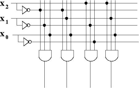
Connect the necessary
inputs to each AND gate in order to contruct the minterms: |
|
|
Dots indicate connections |
|
|
|
|
|
|
|
|
|
|
|
|
|
|
|
|
|
|
|
|
|
|
|
|
|
|
|
|
|
|
|
|
|
|
|
|
|
|
|
|
|
|
|
|
|
|
|
|
|
|
|
|
|
|
|
|
|
|
|
|
|
|
|
|
|
|
|
|
|
|
|
|
|
|
|
|
|
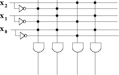
This can be simplified
by combining the inputs for each AND gate: |
|
|
|
|
|
|
|
|
|
|
|
|
|
|
|
|
|
|
|
|
|
|
|
|
|
|
|
|
|
|
|
|
|
|
|
|
|
|
|
|
|
|
|
|
|
|
|
|
|
|
|
|
|
|
|
|
|
|
|
|
|
|
|
|
|
|
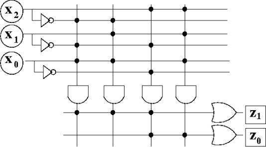
Now add OR gates to
combine the minterms: |
|
|
|
|
|
|
|
|
|
|
|
|
|
|
|
|
|
|
|
|
|
|
|
|
|
|
|
|
|
|
|
|
|
|
|
|
|
|
|
|
|
|
|
|
|
|
|
|
|
|
|
|
|
|
|
|
|
|
The vertical lines are
called the AND plane |
|
|
|
|
The horizontal lines are
called the OR plane |
|
|
|
|
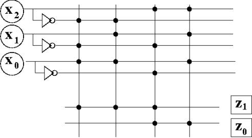
We can simplify the
picture even further by eliminating the gates themselves: |
|
|
|
|
|
|
|
|
|
|
|
|
|
|
|
|
|
|
|
|
|
|
|
|
|
|
|
|
|
|
|
|
|
|
|
|
|
|
|
|
|
|
|
|
|
|
|
|
|
|
|
|
|
Programming the PLA: |
|
|
|
|
|
Make the connections
represented by the black dots |
|
|
|
|
|
|
|
|
|
|
|
|
|
|
|
|
|